
Where the drag actually goes
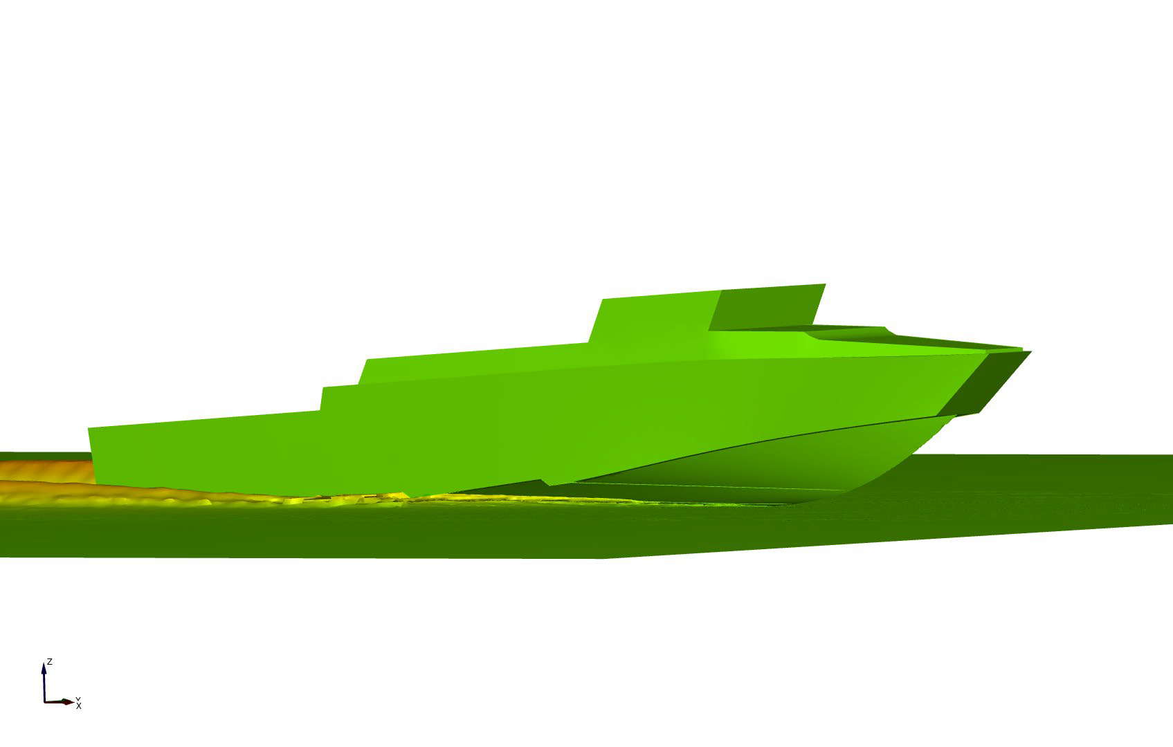
A planing hull throws a sheet of water sideways and pays for it twice: in wetted surface, and in momentum it never gets back. Strakes detach part of that sheet outboard. Deflectors intercept it parallel to the stagnation line and turn it aft, so part of it comes back as forward thrust. Grey is the pressure area doing useful work; orange is spray.
Baseline. The whole spray sheet leaves the bottom sideways, and the momentum in it is never recovered.
Source: Olin, L. (2015), Numerical Modelling of Spray Sheet Deflection on Planing Hulls, MSc thesis, KTH Centre for Naval Architecture. CFD, 7 m hull, 18.6° deadrise, 1350 kg, 40 kn, calm water. These figures isolate the physics on a small hull against an unmodified bottom. What that becomes on a large, already-developed hull is the CB90 case below.
The CB90 case, and why heavier boats get smaller improvments
Two different questions, two different baselines. The KTH figures measure deflectors against a bare bottom with nothing on it. The CB90 is measured against the real hull in service — three decades of development, at 27 tonnes. The second number is smaller, and it is the one that describes what a builder replacing a working design will actually get on a 20 ton+ boat.
So: expect single digits to low teens on a >20 ton boat, more on a hull designed around the deflectors from the start. On the CB90 — the Combat Boat 90 fast assault craft — the gain also climbs steeply with speed — 1.4% at 20 knots, 9.8% at 40, 10.9% at 45 — because the spray energy and resistance grows with speed and there is more of it to recover.
| Speed | Resistance | l / nm | Δ fuel |
|---|---|---|---|
| 20 kn | −1.4% | 11.85 | −2.3% |
| 25 kn | −1.5% | 10.24 | −1.9% |
| 30 kn | −6.3% | 8.92 | −7.4% |
| 35 kn | −6.7% | 8.75 | −7.0% |
| 40 kn | −9.8% | 8.60 | −9.9% |
| 45 kn | −10.9% | 8.92 | −11.2% |
| 49 kn | — | 9.60 | new top speed |
Parametric predictions from Petestep software built on the Savitsky method, including deadrise distribution, strake and deflector effects, drive and aerodynamic resistance, propeller efficiency and slip. Assumes flat water, clean bottom without antifouling, 20 °C, sea level, 57% total drivetrain efficiency. Full RANS CFD on the same hull gives 7% lower resistance at both 40 and 50 knots — the two methods bracket each other.
Vertical accelerations down by a third in head seas
Speed is what gets measured; vertical acceleration is what limits the boat. On the CB90 the deflectors cut impact loads hard enough to change how fast a crew can keep running in a seaway — before any change to engines, structure or seating.
Seakeeping: separate wave simulations, regular Stokes 5th-order waves, 1 m height, 10 m wavelength, head sea at 40 knots. Same load case throughout.
Every figure, with its baseline and its source
Percentages travel badly without a baseline. This is the whole set, what each one is measured against, and which study produced it — so your naval architect can check our arithmetic before the first call rather than after it.
| Measure | Result | Measured against | Source |
|---|---|---|---|
| Top speed, unchanged engines | +3 kn | CB90 original hull, 46 → 49 kn at 27 t with the same 2 × 846 kW package | Petestep parametric prediction, 2026 |
| Fuel per nautical mile | −9.9% | CB90 original hull at 40 kn. −11.2% at 45 kn, −2% at 20 kn — the gain grows with speed | Petestep parametric prediction, 2026 |
| Total resistance | −7% | CB90 original hull at 40 and 50 kn, RANS CFD | Petestep CFD, 2026. Parametric method gives 9.8% at 40 kn on the same hull. |
| Vertical accelerations | −35% / −25% | CB90 original hull. A₁∕₁₀ and A_max, three deflectors, 1 m regular head sea at 40 kn. Two deflectors: −22% / −20%. | Petestep wave simulation, 2026 |
| Wetted area | −12.4% | CB90 original hull at 40 kn, 36.01 → 31.56 m² | Petestep parametric prediction, 2026 |
| Total resistance, isolated physics | −32.1% | Bare hull with no strakes, 7 m boat at 40 kn. Strakes alone reach −18.0% on the same hull, so deflectors are roughly 17% better than strakes in that case. | KTH Centre for Naval Architecture, Olin 2015. Academic CFD, small hull, unmodified baseline. |
| Thrust recovered from spray | 4% | Share of total drag offset by turning the sheet aft — about 20% of the energy in the sheet, against a theoretical ceiling of 60% | KTH Centre for Naval Architecture, Olin 2015 |
Read the underlying documents: Olin 2015, KTH study (PDF) · CB90 performance indications (PDF) · Published by the KTH Centre for Naval Architecture
If you already build stepped hulls
A step ventilates the surface behind it. A deflector works above the water.
These are not two answers to the same question. A transverse step trades wetted area for an air cavity aft of the step face. It does nothing about the spray sheet, which forms forward of the stagnation line and is where a planing hull throws momentum sideways and never gets it back.
And a stepped hull does not have less of that problem. It has more of it. Every planing surface aft of a step forms its own stagnation line and its own spray sheet. A two-step hull has three spray sheets to recover, not one.
- Different region of the hullSteps act on the pressure area aft of the stagnation line. Deflectors act on the spray region forward of it. Neither takes the other's work away.
- Only one of them adds forceA step removes wetted area. A deflector removes wetted area and turns the spray aft, recovering roughly a fifth of the energy in the sheet as forward thrust. No step arrangement does that.
- Across the speed range, not at one pointA step is tuned to a narrow band and can cost you below it. Deflectors are staged: on the CB90, two deflectors were optimal at 50 knots and three at 40, and the gain rises steadily with speed rather than peaking and falling away.
- It carries load as well as waterA deflector can be built into the stringer structure. That means a stiffer bottom for the same internal structure, or the same stiffness for less weight — a step gives you neither.
If your boat model is already stepped, keep the step arrangement. We design the deflectors around it, surface by surface, and simulate the whole running bottom as one system.
How a hull project runs
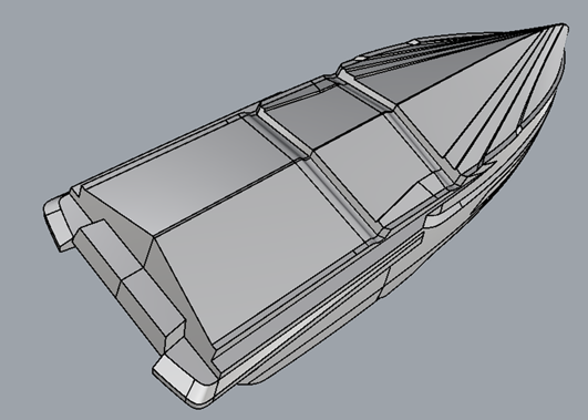
A deflector arrangement is not a part you bolt on. Position, height and section angle all depend on where the stagnation line sits at your speeds and load cases, so the geometry is designed per model — and, on a stepped hull, per running surface.
Specification
We take the boat as you intend to build and sell it, not as an idealised hull.
- LOA, beam, deadrise
- Displacement range, LCG, VCG
- Engine and drive options
- Speed envelope and duty cycle
Simulation
Parametric prediction across the full planing range first, then RANS CFD on the candidate geometries and wave simulation for accelerations — the same sequence that produced the CB90 figures above.
- Stagnation line mapping
- Deflector count and staging
- Height and section angle
- Resistance, trim and fuel curves
Surfaces and trials
You receive the running surface geometry for your plug, and we validate it against the simulation on the water.
- Released hull surfaces
- Predicted speed and fuel curves
- Sea trial support
- Licence agreement
Will it work on your boat?
Deflectors replace strakes on planing V-bottom hulls. They are not a stepped hull and not an alternative to one — on a stepped hull they are designed per running surface. All conventional propulsion works with them: shaft, sterndrive, outboard, waterjet or surface drive. The CB90 case above is a 27-tonne twin waterjet vessel, which is a representative improvement in this class of boat.
- Hull typePlaning V-bottom
- Demonstrated to27 t, 49 kn (CFD)
- PropulsionAny conventional system
- Combines withTransverse steps, per surface
- Applies toNew models and hull revisions
What it costs, and what it gives back
A design engagement for the model, then a licence fee per boat produced. The fee is modest, and there are three separate places a builder recovers it. You can specify a smaller engine for the same top speed, which alone pays the license back many times over. You can also build the deflectors into the stringer structure and take weight out of the internal structure, or keep the weight and gain stiffness. The lower slamming impacts further reduces fatigue and risk of breakdowns and injuries. Overall contributing to a better boat. On boats with many running hours, the fuel savings also contribute to the positive returns, and will continue to do so for the entire service life of the boat.
We are a hull designer and licensor, not a shipyard. We do not build boats and we do not compete with you or our customers.
Apply for analysis of your hull, for free
Tell us about the boat . With the particulars below we can tell you within a week whether deflectors are worth it for this model, roughly what the gain looks like, and what the project would involve. If the boat is not a good fit, we will say so.